Hidden Hidden Hidden Hidden


USING INSTRUNET WITHIN DASYLAB
SOFTWARE > DASYLAB SOFTWARE >

Below are several notes on DASYLab ≥ v7.0 operation with instruNet using version ≥ v11.0.0.152 of the DASYLab/instruNet interface (i.e. "..Program Files \ DASYLab \ iNet.dll").

Block Size
DASYLab is a series of subroutines (icons) that process little segments of data that are BlockSize number of points long. A sequential scheduler tells each icon to execute and process these segments, and continously telling the set of icons to execute. Each segment has a header with a timestamp and the actual data points. Typical Block Sizes are .5secs of data (e.g. all icons execute 2x per second). If Auto Select is selected, DASYLab typically gives you a block size of about 0.5 seconds, or 8192 points, whatever is smaller. Selecting Auto Select is the recommended option.

instruNet Icons
In the newer versions of DasyLab, one accesses instruNet icons under "Modules Input/Output", as shown to the right. In older versions of DasyLab, these icons were accessed from the menubar, under "instruNet".

Low and High Speed Digitize Modes
There are 2 digitizing modes within DASYLab: Low Speed and High speed. Low Speed is sometimes referred to as "Single Value"; and High Speed is sometimes referred to as "waveform" or "continuous". High Speed involves digitizing at the Sample Rate and Block Size specified in the instruNet Timebase dialog. Low Speed involves transferring 1 point at the end of each Block. The instruNet icons are summarized below:

  • The Input icon runs in High Speed mode and connects to analog input channels as well as digital group IN channels (e.g. i4xx Ch29 Uio25_28 IN, i100 Ch25 DioGroup).
  • The Output icon runs High Speed ("Waveform" or "Continuous") or Low speed ("Single Value"), as selected in the module dialog box under "Output Mode". Most voltage output channels support high speed output (e.g. i100 Ch4 Vout, i430 Ch17 & 18), yet not all of them. For example, the i430 Ch19 and Ch20 Vout hardware only support low speed, as noted in the i430 datasheet. The Output icon also supports digital i/o group OUT channels (e.g. i4xx Ch30 Uio25_28 OUT) by outputting an integer value to a group of bits (e.g. 0 to 15 value drives 4bit port). This does not work with the i100 Ch25 Dio Group channel since that channel digitizes as an input and this is output. If you want to do high speed digital output with the i100 then you need to create a Ch26 Digital OUT channel and then select that in the Output icon dialog. Click here for details on how to enable Ch26.
  • The Digital Input icon works with digital i/o channels and only supports Low Speed mode. Inside the icon, click the "Select Channel" button, select a digital group IN channel (e.g. i4xx Ch29 Uio25_28 IN, i100 Ch25 DioGroup), close the channel select dialog, and then click bit enable buttons as needed (to add more bit enable buttons, click the ">" button). If one selects a non digital i/o group IN channel, it might say "select dio channel on i100" -- this alert should read "select digital group IN channel". To input digital high speed, use the Input icon to read an integer value (e.g. 0 to 255 value from 8bit port), and then use DasyLab software to isolate bits as needed.
  • The Digital Output icon works with digital i/o channels and only supports Low Speed mode. Inside the icon, click the "Select Channel" button, select a digital group OUT channel (e.g. i4xx Ch30 Uio25_28 OUT, i100 Ch25 DioGroup), close the channel select dialog, and then click bit enable buttons as needed (to add more bit enable buttons, click the ">" button). To output digital high speed, use the Output icon to output in an integer value (e.g. 0 to 15 drives 4bit port), and use DasyLab software to isolate bits as needed.
  • The Parameter Output icon only runs in Low Speed mode.

Synchronizing Channels with Different Sample Rates and Block Sizes
The displays are influenced by the timestamp attached to the input channels. Data from different sources might have different timestamps causing the Y vs Time display to produce a "synchronization" alert. The Chart Recorder display handles data with different timestamps significantly better than Y vs Time. To synchronize channels with different sample rates and block size, one should use the "Signal Adaption" icon with Operation set to "Full Interpolation". This is sometimes necessary before viewing.

Output Block Delay
When running High Speed output (i.e. "Continous" mode selected within Output icon), one must select a delay between the input and output, in units of blocks. The default is 2 blocks. For example, if the block size is 0.064 seconds (e.g. 1000 ks/sec/ch with block size of 64) and Delays is 2 blocks then one would see a 0.128 second delay between input and output .

Analog and Digital Output
If instruNet is digitizing from the voltage inputs at <1Ks/sec, then DASYLab can write to an output (digital or analog) at the end of every block (via low speed "single value" output mode). For example, if the block size is 64 and the sample rate is 100s/sec, then it will update the output every .64secs. If one wants the output and input rate to be the same, one must set the block size to 1. Combining inputs and outputs works well with <100s/sec/ch rates and block sizes of 1.

Digital Input and Digital Output Icons
When working with Digital Input or Digital Output icons, one must first select an instruNet Digital Input Group channel (e.g. "i100 Ch25 Dio", "i4xx Uio25_28 In", "i460 Uio1_8 In", "i460 Dio9_24 In"). After this, one can enable bits for i/o by pressing the bit enable buttons within the icon itself. The instruNet Direction field, which determines whether a bit is an input or output, is set automatically by DasyLab.

instruNet has its own Timebase
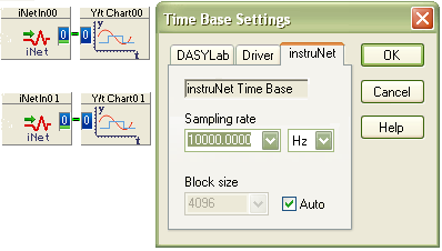
The newer versions of DASYLab have a timebase area for instruNet, as shown in the photo to the right. This is where one sets the sample rate, in units of samples-per-second-per-channel, and also the block size. Setting block to Automatic often works well. The above picture shows digitizing from an analog input channel and a digital i/o group channel (e.g. i4xx Ch29 Uio25_28, i100 Ch25 DioGroup) at 10ks/sec/ch .

Input/Output Feedback Loop
When digitizing waveforms from the a/d while simultaneously outputting to the d/a, we recommend:

  • Set block size to 1.
  • Set Output icon's "Output Mode" setting to "Single Value".
  • If working with the i430:    Since we are running Single Values mode, one can use d/a channels 17 through 20. Note that i430 Ch19 and Ch20 are slower and do not support the High Speed mode (referred to as "Continuous" or "Waveform" in dialog box).
  • Use "Chart Recorder" display instead of "Y/t Chart" display.
  • Remember to press "Select Channel" button to select channel inside of instruNet input/output icons.

Example Worksheets
For example DASYLab/instruNet worksheets, please click here.

Troubleshooting
If you run into trouble, please click here.