Hidden Hidden Hidden Hidden
 

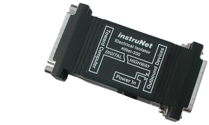
MODEL i330 INSTRUNET
OPTICAL ISOLATOR
PRODUCT LIST > i330 >

The Model 330 Electrical Isolator provides 1000 Volts of optical isolation at one point within an instruNet network.  This is often used to eliminate ground loops between the computer and items under test, and to reduce noise that is transmitted from the computer to sensors.  When measuring small voltages (e.g. <10mV), optical isolation is sometimes critically important.  Multiple Model 330's can be placed in one network (e.g. place one Model 330 every 2 Devices, in an 4 Device network). 

The Model 330 optical-isolator manufactured before November 2010 is referred to as "i330 Revision 1". It is identical to the newer Revision 2, described below, except power is cabled differently. For details on the older Rev 1, click here.

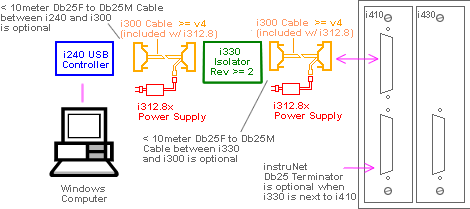
Typical Isolated system with i240 USB controller
The i240 USB controller requires two i312 power supplies when working with the i330 (Rev 2), since each side of the i330 optical isolator requires power, as shown below.


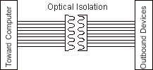
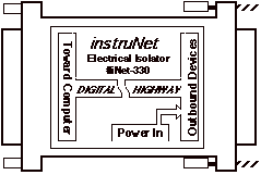
Model 330 Electrical Isolator Block Diagram
The internal circuitry of the i330 (Rev 2) is summarized below.


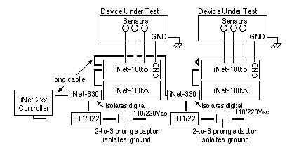
Break Ground Loops and Reduce High Frequecies between Grounds with the i330
If ground loops or high frequencies between grounds are effecting your measurements, one should consider installing an #iNet-330 Optical Isolator. These isolators, the transformer in an external power supply, and a 2-to-3 prong power adapter fully isolate the instruNet measurement box. Once isolated, one can attach 110/220VAC power directly to the instruNet box (i.e. the instruNet GND terminal shorted to AC power !) while performing a measurement without adverse effects (assuming all wires to the box are floating) due to this isolation. However, it is recommended that the instruNet box GND screw terminal be attached to either your device under test ground (which is attached to earth ground), or direclty to earth ground. This will keep the instruNet box ground from radiating with respect to earth ground, as shown in the below illustration. A large #18 gage wire from the instruNet GND terminal to a nearby local earth ground is recommended. An example of an isolated system with 4 instruNet Devices, without ground loops, is illustrated below:

Isolating From Earth Ground
The External Power Input pins 1 and 2 are both tied to the outbound instruNet device ground (case and pcb).  If this is also tied to the 3rd prong of the power supply AC input connector, and you want to isolate instruNet from this earth ground, then you would need to place a 2-to-3 prong Adaptor at the power supply input connector (or rip the 3rd prong out of the plug with a pair of strong pliers).


Fig 6.7  i330 Mechanical Outline

Slower Speeds
Since the optical isolators introduce delays, the Model 330 reduces the speed of the instruNet network from 4M bits/sec to 1.33M bits/sec, on short networks.  In a worse case scenario, this would reduce the maximum sample rate 3 to 1.

Further Reading


Getting Started
Compatibility

Troubleshooting the i330

Wild Grounds
If the outbound devices are not seen by instruNet World, try temporarily holding a wire between the outer shell of the isolator inbound and outbound DB-25 connectors.  If the outbound devices are then seen by instruNet World (after Reset), then this indicates that a very high frequency exists between the two grounds and is causing problems.  The Model 330 is designed to sustain a signal between the two grounds that is 50V peak-to-peak with a 1000V/us slew rate (e.g. slews 1Volt in 1ns); and this is adequate is most applications.

Troubleshooting
Troubleshooting Hardware