Hidden Hidden Hidden Hidden


HOW TO CONNECT A SENSOR TO INSTRUNET
APPLICATIONS >

For a list of compatible sensors and controls, click here. You can also find these listed in the navigation area to your left.

Power OFF While Wiring Sensors & Installing Hardware

To avoid permanent damaged to instruNet hardware:

  • i60x: Unplug USB cable to i60x device while wiring sensors and while plugging into i60x Hd44 Connector
  • i4xx/i555: Remove 110/220 VAC power to i312.8 power supply while wiring sensors and while connecting i51x wiring box to Hd44 Connector
  • i100: Remove 110/220 VAC power to i312.8 power supply while wiring sensors and while attaching Db25 cable
  • i200/i230: Turn computer power off while connecting i200/i230 Controller to Computer


Automatic Sensor Installation via Quick Setup

For a simplified method of sensor installation, see Quick Setup.
Alternatively consider manual setup, described below.


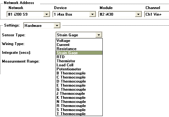
Manual Sensor Installation via Channel Setup

The instruNet voltage input terminals (often labeled "Vin(+)" or "Vin(-)") can directly connect to a variety of sensors, with instruNet software returning values in native engineering units (e.g. degrees Celsius, μStrain, Volts, Amps, ohms).  This requires wiring the sensor to the instruNet hardware in the appropriate manner, and then configuring the instruNet software for your particular sensor, as described in the following steps:

1)  Physically Wire your Sensor to instruNet hardware
The first step is to physically wire your sensor to the instruNet hardware, per the Sensor Setup Instructions. For example, to connect a J Thermocouple, one would attach the positive lead of the thermocouple to the instruNet Vin+ terminal, and the negative lead to the Vin- terminal.

Below is an example wiring diagram for Differential voltage measurement.

2) Tell the instruNet software which Sensor is connected
Set the Sensor popup in the Hardware settings area of the Channel Setup dialog to the correct Sensor (e.g.  Volts, J Thermocouple, etc).  If you are not sure how to set this field, please consult Sensor Setup instructions for the particular device in use.

To set the Sensor popup, one would:

  1. Open the instruNet World window by launching the Windows "instruNet World Win32.exe" application program (e.g. double-click on its icon).
  2. Click on the Network tab at the bottom of the window to select the network page.
  3. Click on the name of your channel in the left-most column to open the Channel Setup dialog.
  4. Select Hardware in the Settings popup menu.
  5. Select the desired sensor in the Sensor popup menu, as illustrated in the above figure.

3) Interview Vs. Manual Setup
When in the Channel Setup dialog, one can either setup a sensor with an interview process that asks the user several questions and then sets all fields based on the responses; or one can set fields manually. If one uses the Interview process, they can ignore all fields, and just make sure the answers to the questions are correct and that the sensor is wired per the recommended wiring diagram. To see this diagram, one can press the User's Manual button in the Channel Setup dialog after setting the Sensor field.

Interview: To start the interview, one must change the sensor field (e.g. Volts to Thermocouple), or press the Interview button in the lower right corner of the Channel Setup dialog. To stop the interview process, press the Cancel button while a question is displayed. When the interview completes, one can skip the below steps 4 through 10 and jump directly to Check Your Work. If you want detailed information on how your sensor has been set up at any time after the Interview process, then press the Sensor Report button in the lower right corner of the Channel Setup dialog.

Manual Setup: If you want to set fields manually, then either stop the interview at the first question, or let the interview complete and then adjust fields after the interview. To adjust fields manually, proceed with Step 4 below.

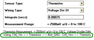
4) Tell the instruNet software how the Sensor is wired
Set the Wiring popup in the Hardware settings area of the Channel Settings dialog to the correct Wiring (e.g. Vin+ - Vin- Differential, Bridge, Voltage Divider, etc). For guidance, please consult Sensor Setup Instructions. Recall that the chosen wiring popup must match your actual physical hardware wiring. For details on how to set up your selected sensor, press the User's Manual button in the lower right corner of the Channel Setup dialog box. After setting the Sensor and Wiring fields, a description of the wiring is displayed above the snapshot display, as noted below:

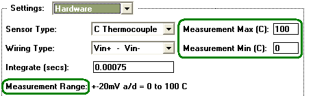
5) Set the appropriate constants as required
Set the fields in the Constants settings area as needed. This involves selecting Constants in the Setting popup, and then setting specific Constants fields as noted in Sensor Setup Instructions. For example, to measure a resistance instruNet needs to know the value of an external shunt resistor "Rshunt", in ohms. This would involve setting the Rshunt Constants fields to correspond to your actual resistor in use.

6) Select the appropriate input range
The Hardware Settings dialog, illustrated to the right, includes fields that set the measurement range.

For example, if one sets up a 0°C to 100°C temperature sensor, then Measurement Min would be set to 0 and Measurement Max would be set to 100. These two fields represent Internal Engineering units (before the Mapping).

If the voltage exceeds a bound, then the bound is returned by the software.  For example, if you input 2V and the range is ±1V, then instruNet will return 1 Volt.  The resolution and accuracy of the measured signal increases when the range is reduced.  For example, typical voltage accuracy is ±10uV in the ±10mV range, and ±0.5mV in the ±5V range with 1ms of integration.  Some sensors require a specific voltage range, or only allow one range.  For example, the range with thermocouples is always ≤ ±80mV.

If one is working with a voltage sensor, one can set the range using either one of the following methods:

  1. Specify range with the Measurement Range popup menu, in Volts units (e.g. ±5V...±0.01V with i430). In this case, the Measurement Min/Max fields are both set to 0.0 internally, to indicated that the Measurement Range popup is in control.
  2. Specify range with the Measurement Min/Max fields, in Volts units. This is initiated by selecting "Explicit" in the Measurement Range popup menu. To revert back to popup menu control, set both Min and Max fields to 0.

If one is working with a non-voltage sensor (e.g. thermocouple, resistance, current), one can set the range using either one of the following methods:

  1. Specify range with the Measurement Min/Max fields, in Internal Engineering units (before the Mapping).
  2. Specify range with the Measurement Range popup menu, in Volts units. This is initiated by setting both Measurement Min/Max fields to "0" or "auto". To revert back to Min/Max control, set both Min and Max fields as desired.

7) Set up analog anti-aliasing filters as needed
If working with i500 analog filter daughterboards, install them onto your i423 card(s) before installing the i423 into the card cage, as noted here. Also, carefully follow the i500 software set up instructions, described here. For a summary of anti-aliasing filters and why you might need them, click here.

8) Set the Integrate field
Set the Integrate field in the Hardware Settings area as needed.  This selects the duration that the signal is averaged before instruNet returns one number.  For example, if you choose 0.016666 seconds (one 60Hz line cycle), it will return the average signal value over a period of 16.6mSec.  This is helpful at reducing noise for signals acquired at slow sample rates (e.g.  to integrate 0.016 seconds worth of data the sample rate must be greater than 0.016 seconds per point, or slower that 60samples/second).  Each hardware device offer different Integrate options. For details, see Sample Rate Vs Integration Vs. Noise.

9) Select the appropriate Analog Filter
Set the analog Low Pass filter popup in the Hardware Settings area as needed (e.g. i423 options are off, 6Hz, or 4KHz).  Each hardware device offers different analog low pass filter options (not all devices support hardware analog filtering).  Low pass filters cause high frequencies to be rejected, while low frequencies are passed.  Visually, the signal becomes "smoother".  To see the effects of various filters, view the digitized signal at the bottom of the Channel Setup dialog, after making different selections (you might not be able to do this until you are further along in the set up process).

10) Set your Digital filters as needed
If you need to do a digital low pass, high pass, band pass, or band stop filter on your digitized waveform, please set the fields in the filter Settings areas (e.g. Low Pass, High Pass) as desired.  Digital filters are run on the waveform post acquisition, and only effect digitized waveforms (not single values read by instruNet). Please refer Setting Digital Filters for an expanded discussion of this powerful feature.

11) Consult the Sensor Reference for specifics
Carefully implement the Sensor Setup Instructions for your particular sensor.  Different sensors require different range, filter, and constants settings; and care should be taken to insure accurate results. 

12) Set Display Vertical Scale
To adjust the vertical scale of the display, select Display in the Setting popup, and then set the Display Max and Display Min fields to the desired engineering units values that correspond to the top and bottom of the display (e.g. set 1 and -1 to view a signal that varies from -1V to 1V).  Press the Enter or Update button to cause the new settings to take effect, and then view the updated display. If one does not explicitly set the display max/min fields, then the display automatically reverts to the measurement min/max values (i.e. link to measurement min/max). For details, see Display Tutorial, Display Reference, and Measurement Range

13) Check your Work
To check your work, view the incoming signal, in realtime, at the bottom of the Channel Setup dialog.

This display shows the sensor's value, in realtime, in native engineering units (e.g. Volts, Amps, degrees Celsius, strain) based on your software settings and external hardware wiring.  The numerical value displayed at the bottom right is the actual real time value being read by instruNet.  The plot shows the digitized version of your sensor value vs. time.  The horizontal scale of this display is determined by the Points per Scan, Number of Scans, Scan Mode, Horiz Scale, and Sample Rate fields within the global Setup dialog (i.e. press the Record tab at the bottom of the instruNet World window, and then press the Setup button at the top). For details on how these work, please consult Working with the Voltage Inputs

14) Calibration
If interested in Calibration, please see the following resources:


15) If your Sensor is not working, Fix it !
Listed below are several debugging hints for channels that are returning "bad" results:

a.   Troubleshooting Load Cell and Strain Gage Sensors
If working with a load cell or strain gage sensor, click here.

b.   Troubleshooting Thermocouples
If working with a thermocouple, click here.

c.  Examine Sensor Report
To see a list of expected voltages at the various nodes within your sensor circuit, along with other set up data, press the Sensor Report button while in the Channel Setup dialog. If working with instruNet version ≥ 3.4.0.5 (file "iNet32.dll") you will also see printed either "RANGE OK" or "RANGE ERROR". RANGE ERROR indicates the system is trying to measure a voltage that exceeds the electrical measurement range (e.g. trying to read 52mV on ±40mV measurement range). This could be caused by a wiring error, bad sensor, or set up problem. From within the Channel Options dialog one can view sensor documentation by clicking the User's Manual button. To check your software version, select ABOUT in the instruNet World HELP menu; and to update for free, click here.

d.   Check that you have the correct channel
To check that you have the correct channel, and that it is being digitized by the software, view the Channel Setup dialog display as you disconnect one wire from your sensor. The value printed in the dialog lower right corner should change, to indicate that your displayed value is in some way connected to that wire. Also, if you touch the input terminal with your finger, you should notice some slight variation since your body acts as an antenna and causes radio stations, and such, to drive the input terminal (due to its high input impedance).

e.   Check that instruNet is correctly measuring the voltage
At any time, you can set the Sensor popup to Volts, and set the Wiring popup to Vin+ - Vin- to cause instruNet to measure the voltage between the Vin+ and Vin- terminals.  The measured voltage appears in the Channel Setup dialog lower right.  You can then check this against a handheld volt meter that is placed in parallel between the Vin+ and Vin- terminals.  Remember to set the Range popup if your signal is "clipping" on a bound.  To measure the voltage between your Vin screw terminal (Vin+ or Vin-) and ground, you would do the same thing, yet select Vin - Gnd in the Wiring popup.

f.   Check the engineering units calculations
If your voltage looks good, yet the returned engineering units value looks bad, then pull out a calculator (or better yet, a spreadsheet) and run your constants and known values into the equations listed in the Sensor Reference to check the processing of these numbers.  Perhaps one of the fields in the Constants settings area is not set correctly.

g.   Make sure you do not exceed the maximum input voltage
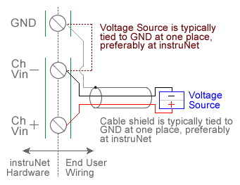
Make sure you are not exceeding the maximum input voltage, with respect to the Gnd terminal.  To check this, measure the voltage between the Vin+ (or Vin-) terminal and the Gnd terminal with a handheld volt meter. For example, in the Model i430, this voltage must not be less than -10V or greater than +10V.  Exceeding a maximum typically does not cause damage unless it is very large (e.g. greater than ± 20V).

h.   Check your ground connections
If the ground between the instruNet device and your signal source is unstable, then connecting a wire between the instruNet Gnd terminal, and your signal source ground might help (e.g. attach a wire between the GND and Vin(-) terminals).  Alternatively, if the instruNet Gnd is tied to the ground of your signal source, and these are at different voltages with respect to Earth ground (commonly referred to as a "Ground Loop"), then current will flow between them.  This current will cause voltage drops and subsequently may induce weird effects -- breaking this ground connection might help.  The best way to determine what helps is to try different things (e.g. hold a wire between two grounds) and observe what happens in the display at the bottom of the Channel Setup dialog. If a ground loop is a serious problem and one wants to eliminate it entirely, then consider working with the electrically isolated i601.

i.   Recheck your work
Recheck your hardware wiring and software settings.

j.   More Things to Try
For more hints on sensor troubleshooting, click here.

15) Save your work. 
To save the current configuration of instruNet (i.e. the settings displayed in the Network page and accessed via the Channel Setup dialog), press the Network tab at the bottom of the window to select the Network page, and then press the Save button at the top of the window to save the settings to disk.  A file save dialog appears, and it is here that you must specify a file name and file location (remember where you put it).

To check your saved settings: exit instruNet world, re-enter instruNet (e.g. launch "instruNet World Win32.exe" Windows application program), press the Network tab at the bottom of the window to select the Network page, press the Open button at the top of the window, select your saved settings file (this will load your save settings), click on the channel that you just set up, and then view the realtime display at the bottom of the Channel Setup dialog.

Alternatively, one could press the Store button to save the settings directly to a preferences file in the operating system folder, and then press the Restore button, at a later date, to restore them.  The advantage of Save/Restore is the user does not need to specify a file name or file location; whereas the disadvantage is the saved file is overwritten the next time someone presses Store.

Further Reading