Hidden
Hidden
Hidden
Hidden
Hidden
Hidden
Hidden
STRAIN GAGE MEASUREMENT (e.g. uStrain)
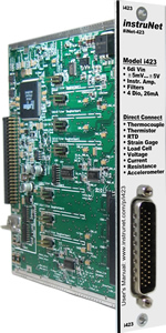
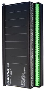
The following instruNet hardware supports Strain Gage Measurements (i.e. measures μStrain of bending or twisting material):
For quick setup instructions, click here. instruNet hardware supports the measurement of Bending or Twisting (Axial) strain; and also supports ¼, ½, and Full Bridge devices. To set up one of these configurations, please click on one of the below options.
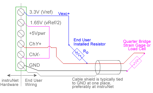
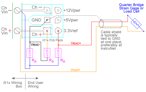
Strain Gage Measurement, ¼ Bridge (µStrain) Strain Gage Measurement, ¼ Bridge (µStrain) Strain measurement using a ¼ bridge circuit involves wiring a strain gage as one leg of a full-bridge circuit, applying a voltage across the bridge, and measuring the voltage across the two intermediate bridge nodes via a pair of instruNet Vin+ and Vin- input terminals. The excitation voltage for the bridge is supplied either by instruNet or by an external voltage source. In below figures a/b/c, component RGAGE is a strain gage, Ro is either a fixed resistor of known value or a fixed unstrained strain gage of value RGAGE, and RLEAD is the lead wire resistance. instruNet calculates the value of the strain, returning "strain" engineering units, using the equations:
VRATIO (V/V) = ((Vin+ - Vin-) - VINIT) / VOUT
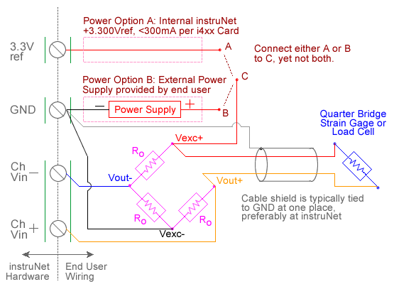
RGAGE, RLEAD, GF, VINIT and VOUT are fixed values that are specified by the user in the Constants Settings area, whereas (Vin+ - Vin-) are measured in realtime by instruNet. Ro and Unstrained-RGAGE must be the same value (e.g. 350ohms) in order for the bridge to operate properly 4. For more details, please see Maximizing Strain Gage Accuracy, Load Cells, Shunt Resistors, 10V External vs. 3.3V Internal Excitation and Voltage Ratio Measurements. To do strain gage measurement using a ¼ bridge circuit you must wire your sensor per the above diagram and then set up your software via the Interview process (started after selecting sensor type in Channel Setup dialog) or by manually running through the below steps: 0. Make sure you are using instruNet software version ≥ 3.4.0.5 (i.e. file "iNet32.dll"). To check your version, select ABOUT in the instruNet World HELP menu; and to update for free, click here. 1. Set the Sensor field in the Hardware settings area to Strain Gage. 2. Set the Measurement Range in the Hardware settings area. For details, click here. 3. Set the Ro field in the Constants settings area to the value of one Ro bridge completion resistor, in ohms units. This is specified in the strain gage datasheet and/or package label. 3, 4 4. Set the GF field in the Constants settings area to the gage's gage factor (also noted in gage datasheet). 9 5. If working with hardware that has variable internal excitation (e.g. i100 ± 5V), then set the Vout field in the Constants settings area to the desired excitation voltage 2, 11. Alternatively, if applying an external excitation voltage, enter -RGAGE value in the Ro edit field (e.g. -350 instead of 350 ohms) to tell the software that the excitation is external, and then enter the external excitation voltage in the Vout field. For more information on excitation, see 10V External vs. 3.3V Internal. 6. Set the delta, Rlead field in the Constants settings area to the resistance, in ohms, of the wires leading to the bridge (0 ohms is typically ok). 7. Set the Vinit field in the Constants settings area to the voltage measured when the bridge is unstrained, in Volts units. 8 8. Set the Wiring field in the Hardware settings area to Quarter Bridge. 9. Capacitors across the voltage input terminals are highly recommended with the i100 (not with the i420/i430/i60x 12) for reducing errors caused by RFI. With 350ohm gages, 0.1uF caps create a low pass filter at 4KHz [4K = 1 / (6.28 * 350 * 0.1e-6)], and are ideal at minimizing RFI effects. 10. Wire your voltage source per figure a, b or c. Click here if you need more guidance setting up the software, click here for information on how to calibrate your sensor, and click here if the measured value is not correct. 5, 10 Strain Gage Measurement, ½ Bridge, Bending (µStrain)
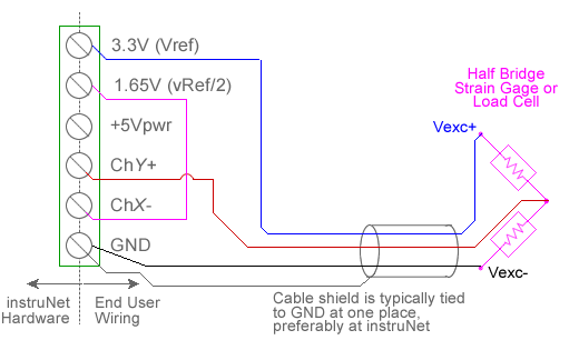
Measuring bending strain using a ½ bridge configuration involves wiring two strain gages as shown above or in figure f, applying a voltage across the bridge, and measuring the voltage across the two intermediate bridge nodes via a pair of instruNet Vin+ and Vin- input terminals. The excitation voltage for the bridge is supplied either by instruNet or by an external voltage source. In figure f; RGAGE is a strain gage, Ro is either a fixed resistor of known value or a fixed unstrained strain gage of value RGAGE, and RLEAD is the resistance of the wire routine to RGAGE. instruNet calculates the value of the strain, returning "strain" engineering units, using the equations:
VRATIO (V/V) = ((Vin+ - Vin-) - VINIT) / VOUT
RGAGE, RLEAD, GF, VINIT and VOUT are fixed values that are specified by the user in the Constants Settings area, whereas (Vin+ - Vin-) are measured in realtime by instruNet. Ro and Unstrained-RGAGE must be the same value (e.g. 350ohms) in order for the bridge to operate properly 4. To do a bending Strain Gage measurement using a ½ bridge circuit you must: 1. Do steps #0 through #7 listed in the previous "Strain Gage Measurement - ¼ Bridge" discussion. 2. Set the Wiring field in the Hardware settings area to Half Bridge Bending. 3. Wire your voltage source per one of the above figures. Click here if you need more guidance setting up the software, click here for information on how to calibrate your sensor, and click here if the measured value is not correct. 5, 10 Strain Gage Measurement, ½ Bridge, Axial (µStrain) Measuring axial strain using a ½ bridge configuration involves wiring two strain gages as shown in figure h, applying a voltage across the bridge, and measuring the voltage across the two intermediate bridge nodes via a pair of instruNet Vin+ and Vin- input terminals. The excitation voltage for the bridge is supplied either by instruNet or by an external voltage source. In figure h; RGAGE is a strain gage, Ro is either a fixed resistor of known value or a fixed unstrained strain gage of value RGAGE, and RLEAD is the lead wire resistance. instruNet calculates the value of the strain, returning "strain" engineering units, using the equations:
VRATIO (V/V) = ((Vin+ - Vin-) - VINIT) / VOUT
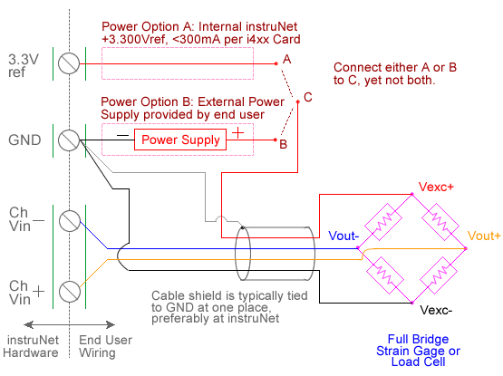
v (Poisson), RGAGE, RLEAD, GF, VINIT and VOUT are fixed values that are specified by the user in the Constants Settings area, whereas (Vin+ - Vin-) are measured in realtime by instruNet. Ro and Unstrained-RGAGE must be the same value (e.g. 350ohms) in order for the bridge to operate properly 4. To do axial Strain Gage measurement using a ½ bridge circuit you must: 1. Do steps #0 through #7 listed in the previous "Strain Gage Measurement - ¼ Bridge" discussion. For details on how to interface to an i512 Wiring Box, click here. 2. Set the Wiring field in the Hardware settings area to Half Bridge Axial. 3. Set the v_Poisson field in the Constants settings area to the poissson value of the material that you are twisting (e.g. aluminum is 0.32). 4. Wire your voltage source per figure h. Click here if you need more guidance setting up the software, click here for information on how to calibrate your sensor, and click here if the measured value is not correct. 5, 10 Strain Gage Measurement, Full Bridge, Bending (µStrain) Measuring bending strain using a full bridge configuration involves wiring four strain gages as shown in figures m and n, applying a voltage across the bridge, and measuring the voltage across the two intermediate bridge nodes via a pair of instruNet Vin+ and Vin- input terminals. The excitation voltage for the bridge is supplied either by instruNet or by an external voltage source. instruNet calculates the value of the strain, returning "strain" engineering units, using the equations: VRATIO (V/V) = ((Vin+ - Vin-) - VINIT) / VOUT
GF, VINIT and VOUT are fixed values that are specified by the user in the Constants Settings area, whereas (Vin+ - Vin-) are measured in realtime by instruNet. To do bending Strain Gage measurement using a Full Bridge circuit you must: 1. Do steps #0 through #7 listed in the previous "Strain Gage Measurement - ¼ Bridge" discussion. 2. Set the Wiring field in the Hardware settings area to Full Bridge Bend. 3. Wire your voltage source per figure m or n. Click here if you need more guidance setting up the software, click here for information on how to calibrate your sensor, and click here if the measured value is not correct. 5, 10 Strain Gage Measurement, Full Bridge, Axial I (µStrain) Measuring axial strain using a full bridge configuration involves wiring four strain gages as shown in either figures p or r, applying a voltage across the bridge, and measuring the voltage across the two intermediate bridge nodes via a pair of instruNet Vin+ and Vin- input terminals. The excitation voltage for the bridge is supplied either by instruNet or by an external voltage source. instruNet calculates the value of the strain, returning "strain" engineering units, using the equations: VRATIO (V/V) = ((Vin+ - Vin-) - VINIT) / VOUT
v (Poisson), GF, VINIT and VOUT are fixed values that are specified by the user in the Constants Settings area, whereas (Vin+ - Vin-) are measured in realtime by instruNet. To do Axial Strain Gage measurement using a Full Bridge circuit you must: 1. Do steps #0 through #7 listed in the previous "Strain Gage Measurement - ¼ Bridge" discussion. 2. Set the Wiring field in the Hardware settings area to Full Bridge Axial I. 3. Set the v_Poisson field in the Constants settings area to the poisson value of the material that your are twisting (e.g. aluminum is 0.32). 4. Wire your voltage source per figure p. Click here if you need more guidance setting up the software, click here for information on how to calibrate your sensor, and click here if the measured value is not correct. 5, 10 Strain Gage Measurement, Full Bridge, Axial II (µStrain) Measuring axial strain using a full bridge configuration involves wiring four strain gages as shown in figure r, applying a voltage across the bridge, and measuring the voltage across the two intermediate bridge nodes via a pair of instruNet Vin+ and Vin- input terminals. The excitation voltage for the bridge is supplied either by instruNet or by an external voltage source. instruNet calculates the value of the strain, returning "strain" engineering units, using the equations: VRATIO (V/V) = ((Vin+ - Vin-) - VINIT) / VOUT
v (Poisson), GF, VINIT and VOUT are fixed values that are specified by the user in the Constants Settings area, whereas (Vin+ - Vin-) are measured in realtime by instruNet. To do Axial Strain Gage measurement using a Bridge circuit you must: 1. Do steps #0 through #6 listed in the previous "Strain Gage Measurement - ¼ Bridge" discussion. 2. Set the Wiring field in the Hardware settings area to Full Bridge Axial II. 3. Set the v_Poisson field in the Constants settings area to the poisson value of the material that your are twisting (e.g. aluminum is 0.32). 4. Wire your voltage source per figure r. Click here if you need more guidance setting up the software, click here for information on how to calibrate your sensor, and click here if the measured value is not correct. 5, 10 Strain Gage Math
where:
|